It's 9:30 on a Monday evening in Bengaluru, and Ananya opens the weekly stand-up for her team. Dev joins from the office down the road. Lucia joins from her flat in São Paulo, Kenji from Tokyo, Sara from Toronto, and Tom from a phone on a commuter train outside London. Ananya leans towards her laptop and asks, "Can everyone hear me?" Five faces nod. Tom says "Yes, loud and clear," and Ananya hears him before she's finished taking a breath.
That exchange seems ordinary, and it hides a hard problem. Ananya's voice has to cross about 8,000 kilometres to reach Tom, and a conversation only feels natural if it gets there in well under half a second. Between them, the internet drops packets, delivers them out of order and late, and Tom's train keeps moving between cell towers, so his bandwidth changes by the minute. Tom's phone sits behind a home router and a mobile carrier that both hide it from the rest of the internet. And six people each sending video to five others is thirty streams, which Tom's phone could never upload or download on its own.
In this case study we'll design the system that carries that meeting, the way an engineer would: start with the most obvious design, find exactly where it breaks, and fix it, one step at a time. The question we'll keep coming back to is this: when Ananya speaks, how does her voice and face reach five people on four continents within a fifth of a second, and keep arriving when one of their networks is bad? Along the way we'll go from boxes on a diagram down to the bytes of a packet header, a buffer that hides the network's hiccups, the layers of a video stream, and the arithmetic of a congestion controller.
01What we're building, and how big
1.1What it has to do
Strip away the chat, whiteboards and webinars, and the core of Zoom is a short list:
- Join a meeting: find the meeting from its ID, let the host admit people, and connect everyone.
- Carry live audio and video from every participant to every other participant.
- Adapt to each person's network and screen, so a phone on a train and a desktop on fibre both get something usable.
- Share a screen, with text sharp enough to read.
- Keep it private: nobody outside the meeting can watch or listen, and, if the host asks, not even the company running the servers.
And the qualities it needs while doing that:
- Fast: a voice must arrive quickly enough that people can interrupt each other naturally.
- Resilient: a few lost packets must not freeze the picture or break the sound.
- Fair to weak links: one participant on a bad network mustn't drag everyone else down.
- Scalable: a meeting of two and a meeting of a thousand should both work.
This list differs from the earlier case studies in one important way. WhatsApp (chapter 49) and Uber (chapter 50) both have to be correct: a message delivered exactly once, one driver per trip. A video call has almost no state worth protecting. A packet of audio that arrives late is useless, because the moment it was meant to be played has passed. So the whole design is shaped by one resource, time, and most of this case study is about spending it carefully.
1.2How big is it?
Zoom's growth in early 2020 is the best-known scaling event in this field. In a letter to users on 1 April 2020, CEO Eric Yuan wrote that at the end of December 2019 the maximum number of daily meeting participants was about 10 million, and that in March 2020 it passed 200 million. On 22 April Zoom announced 300 million. A week later it corrected the wording: these were daily meeting participants, which counts a person once for every meeting they join, and not daily users. Even so, the load grew roughly thirtyfold in four months.
A single meeting can hold up to 1,000 participants, according to Zoom's cryptography whitepaper (version 4.7, June 2025). Zoom's support pages give the bandwidth each participant needs, as of 2025:
| What | Upload | Download |
|---|---|---|
| Audio only | 60–80 kbps | 60–80 kbps |
| 1:1 video, 720p | 1.2 Mbps | 1.2 Mbps |
| Group video, 720p | 2.6 Mbps | 1.8 Mbps |
| Group video, 1080p | 3.8 Mbps | 3.0 Mbps |
| Gallery view, 25 tiles | 2.0 Mbps |
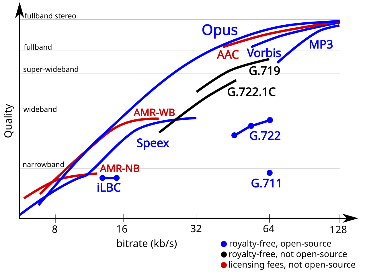
Notice two things in that table. Both audio and video are compressed before they're sent, by a program called a codec (coder–decoder) that squeezes sound or pictures into a few bytes and expands them again at the other end. Audio is tiny next to video, roughly a twentieth of a 720p stream, which is why the design can afford to protect audio much more aggressively than video. And in a group call the upload is larger than the download. That seems backwards, and it's a clue to section 5: each sender uploads more than one version of its video.
1.3The latency budget
What shapes this design most isn't a bandwidth. It's the delay from Ananya's mouth to Tom's ear, which engineers call mouth-to-ear latency. The ITU's planning guide for telephone networks, Recommendation G.114 (2003), says one-way delay should not exceed 400 milliseconds for general planning, and that delays below about 150 ms are close to unnoticeable for most conversations. Past a few hundred milliseconds, people start talking over each other, stopping, and saying "no, you go ahead".
Bengaluru to London is about 8,000 km. Light in optical fibre travels at about 200,000 km per second. How much of a 150 ms budget does the distance alone use up, before any computer touches the packet?
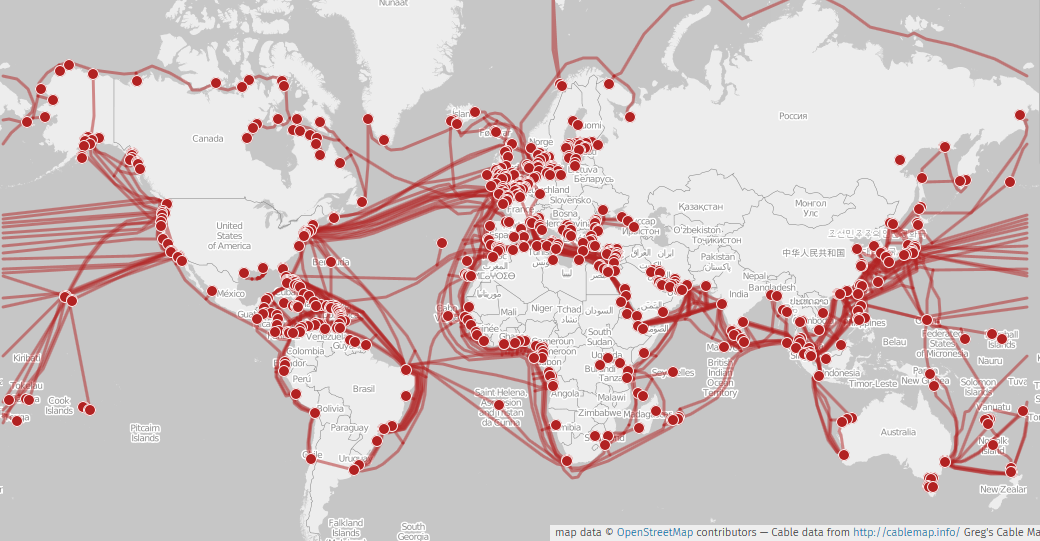
Here is roughly where the time goes on a good call. These are typical figures for the steps any video-calling system has to take, not measurements of Zoom, whose internal numbers aren't published:
| Step | Rough time | Why it costs that |
|---|---|---|
| Collect one audio frame | 20 ms | The encoder needs a chunk of sound to compress; 20 ms is Opus's default frame |
| Encode | a few ms | Compression work on the sender |
| Network, Bengaluru to London | 50–100 ms | Distance, routing and queues in routers |
| Server forwarding | about 1 ms | Read a packet, decide who gets it, send copies |
| Jitter buffer | 20–60 ms | Waiting for late packets (section 6) |
| Decode and play | a few ms to 10 ms | Decompression and the sound card's own buffer |
| Total | roughly 100–200 ms |
Two rows in this table are under the designer's control, and they're the subject of most of this chapter. The network row depends on which servers the call passes through (section 8) and whether packets wait in queues (section 7). And the jitter buffer row is a deliberate trade between delay and smoothness (section 6). Everything else is close to fixed.
02Version 1: everyone sends to everyone over TCP
2.1The obvious design
The most obvious design reuses what every programmer already knows. Each participant's app opens a TCP connection to every other participant, the same reliable byte stream that carries web pages and file downloads (chapter 10). Each app captures a frame of audio and video, compresses it, and writes the bytes to each connection. A small server, the signalling server, does the bookkeeping that isn't media: it holds the meeting ID, tells each newcomer the addresses of the people already in the meeting, and announces who joined and left. Media itself goes directly between participants.
This design breaks in three places, and each one gets its own fix. TCP itself turns a lost packet into a long silence, which the rest of this section fixes. Tom's phone usually can't accept a connection from anyone, which section 3 fixes. And six people each uploading five copies of their video is more than a phone can send, which section 4 fixes.
2.2Why TCP hurts live audio
TCP promises that every byte arrives, in order. To keep that promise, when a packet is lost the receiver can't hand any later bytes to the app until the lost one has been resent and has arrived. Suppose packet 1,001 of Ananya's audio is dropped by a busy router somewhere near Frankfurt. Tom's phone receives 1,002, 1,003 and 1,004 perfectly well, but TCP holds them back, because handing them over would break the in-order promise. This stall is called head-of-line blocking: one missing packet at the front of the line blocks everything behind it.
Ananya's audio is travelling over TCP to Tom, with a round trip of about 150 ms. One packet is lost. Roughly how long is the sound behind it held up?
For a file download, waiting for the lost packet is exactly right, because the file is worthless with a hole in it. For a conversation it's exactly wrong. If packet 1,001 carried 20 ms of Ananya's voice, it's better to play everything else on time and paper over the 20 ms gap with a guess. That trade, losing a little instead of waiting, is the first design decision.
What should carry live audio and video?
- Every byte arrives
- Passes almost every firewall on port 443
- One loss stalls everything behind it for a round trip or more
- Halves its rate on loss, even random wireless loss
- A lost packet costs only itself
- The app chooses: conceal, repair with redundancy, or ask again
- The app must build its own ordering, timing and congestion control
- Some corporate networks block UDP
Every mainstream calling system carries media over UDP, and Zoom is no exception. Its architecture documents (2024) say that "UDP is used when available, with seamless fallback to TCP/TLS (including HTTPS/443) in more restrictive environments." The fallback matters: some offices block everything except web traffic, and a call that's slightly worse over TCP beats no call at all.
2.3RTP: numbering and timing each packet
UDP delivers datagrams, and that's all. It doesn't say which sender a packet came from, where it falls in the sequence, or when its contents should be played. So every calling system puts a small header in front of the media, and the standard one is the Real-time Transport Protocol (RTP), defined in RFC 3550 (2003). Its fixed header is 12 bytes:
| Bits | Field | What it's for |
|---|---|---|
| 2 | version | Always 2 |
| 1 | padding | Extra bytes at the end, for encryption block sizes |
| 1 | extension | A header extension follows (used for things like video layer IDs, section 5) |
| 4 | CSRC count | How many contributing-source IDs follow (used when a server mixes streams) |
| 1 | marker | For video, "this is the last packet of a frame" |
| 7 | payload type | Which codec this is, for example Opus or H.264 |
| 16 | sequence number | +1 for every packet; how the receiver spots loss and reordering |
| 32 | timestamp | When the first sample in this packet was captured, in codec clock ticks |
| 32 | SSRC | A random ID for this stream, so the receiver can tell streams apart |
Sequence number and timestamp do different jobs, so let's be precise about which. The sequence number counts packets. If Tom sees 1,000, 1,002, 1,003, he knows 1,001 is missing, or late. The timestamp counts time in the media's own clock: 48,000 ticks a second for Opus audio, 90,000 for video. A video frame is often split across several packets, and they all carry the same timestamp, because they belong to the same moment. Timestamps let the receiver play things at the right pace and line up Ananya's lips with her voice, even though audio and video travel as separate streams.
?What happens when the 16-bit sequence number runs out?
Sixteen bits only count to 65,535. Audio at 50 packets a second wraps around after about 22 minutes, and a busy video stream at several hundred packets a second wraps in a couple of minutes. So the receiver never compares sequence numbers directly. It treats them as positions on a circle: packet a is "after" packet b if (a − b) mod 65,536 is less than 32,768. That way 3 comes after 65,534, as it should. Receivers also keep a count of how many times the number has wrapped, giving an "extended" 32-bit sequence number for statistics.
Alongside RTP runs its companion, the RTP Control Protocol (RTCP). Every few seconds each receiver sends back a receiver report: the fraction of packets lost since the last report (an 8-bit fraction), the total lost, the highest sequence number seen, and an estimate of the jitter, which section 6 explains. Ananya's app uses these reports to learn how its stream is faring at the far end, and RFC 3550 limits them to about 5% of the session's bandwidth so the feedback doesn't crowd out the media.
?Does Zoom use RTP?
Zoom hasn't published its wire protocol, but two outside studies looked. In April 2020 the Citizen Lab found that Zoom's protocol "appears to be a bespoke extension of the existing RTP standard", carried mostly over UDP port 8801 between clients and Zoom's servers. In 2022 a team at Princeton reverse-engineered the format for a measurement paper at the Internet Measurement Conference. They found a proprietary Zoom header, then a standard RTP header whose position depends on the media type, then, for video, a header for H.264 (the most widely used video codec) followed by the encrypted media. So the bookkeeping is standard RTP inside Zoom's own wrapper.
03Reaching a phone that can't be reached
3.1Addresses that only exist at home
Version 1 had Tom's app open a connection straight to Ananya's laptop. That almost never works, and Ananya's own flat shows why. Her laptop's address is something like 192.168.1.23, a private address that only means anything on her home network. Thousands of homes use exactly the same addresses. Her home router has one public address on the internet and shares it between every device inside.
Her router does this with a table. When Ananya's laptop sends a packet out from its port 5000, the router rewrites the source to its own public address and some free port, say 61,234, and records the pair. When a reply comes back to port 61,234, the router looks it up, rewrites the destination to 192.168.1.23:5000, and passes it in. This rewriting is called network address translation (NAT), and the version that maps many devices onto one address by port is NAPT.
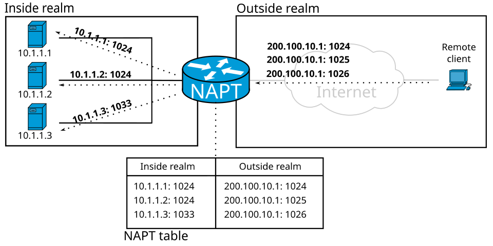
Look at what that means for Tom. If Tom's phone sends a packet to Ananya's router out of the blue, the router has no table entry for it and drops it. Tom's phone is in the same position, usually twice over: mobile carriers put phones behind their own large NATs. Neither side can be reached by the other, because each side's router only lets in replies to things that side sent first.
3.2STUN, TURN and ICE
A fix comes in three pieces, each covering a case the previous one can't.
First, find out what you look like from outside. Ananya's laptop sends a small request to a server on the public internet, and the server replies "your packet came from 203.0.113.7, port 61,234". That reply tells the laptop its public address and port, the ones its router just created. This protocol is STUN (Session Traversal Utilities for NAT, RFC 5389 in 2008, updated as RFC 8489 in 2020).
Now Ananya and Tom swap their public addresses through the signalling server, and both send packets to each other at the same moment. Ananya's outgoing packet creates an entry in her router, so when Tom's packet arrives a moment later it looks like a reply and gets in. Tom's router does the same for Ananya's. This trick is called hole punching, and with most home routers it works.
With some it doesn't. Certain NATs, common in corporate and carrier networks, pick a different public port for every destination, so the address Ananya learned from the STUN server is useless for talking to Tom. For those cases there's a relay. Both sides send their media to a server on the public internet, which forwards it to the other. Each side only ever talks outwards to the relay, which every NAT allows. This is TURN (Traversal Using Relays around NAT, RFC 5766 in 2010, updated as RFC 8656 in 2020). A TURN relay always works, but every packet takes a detour and the relay's operator pays for the bandwidth.
So which should Tom's app use? It doesn't know in advance, so it tries them all. That procedure is ICE (Interactive Connectivity Establishment, RFC 8445, 2018). Each side gathers a list of candidates, addresses where it might be reachable:
| Candidate type | Where it comes from | Recommended type preference |
|---|---|---|
| host | The device's own address | 126 |
| peer-reflexive | Learned during the checks themselves | 110 |
| server-reflexive | The public address a STUN server reported | 100 |
| relayed | An address on a TURN relay | 0 |
Each candidate gets a priority, computed as 2²⁴ × type preference + 2⁸ × local preference + (256 − component ID). Direct paths win over relayed ones by a huge margin, because the type preference sits in the top bits. Both sides swap candidate lists through the signalling server, pair every local candidate with every remote one, and send STUN checks down each pair in priority order. Whichever pairs get answers first are used, so a direct path is chosen when it exists and the relay only when nothing else works.
?Does Zoom do all this for every call?
Mostly it doesn't need to, for a reason that leads straight into the next section. In a normal Zoom meeting every participant's app connects outwards to one of Zoom's media servers, which has a public address and listens on a known port. An outgoing connection to a public server is exactly the case every NAT handles, so there is no hole to punch. Zoom's documentation says that a meeting of just two people can use a direct peer-to-peer connection, and the 2022 Princeton study saw exactly that: each peer-to-peer session was preceded by a STUN exchange with a Zoom server.
04Who sends what to whom
4.1The cost of a full mesh
Suppose ICE has worked and every pair of participants can reach each other. Version 1 still has a problem of arithmetic.
Six people are in Ananya's meeting, each sending 720p video at about 1.2 Mbps. In version 1, every participant sends a separate copy to each of the others. How much does each person upload and download? Tom's phone on the train can upload about 1 Mbps.
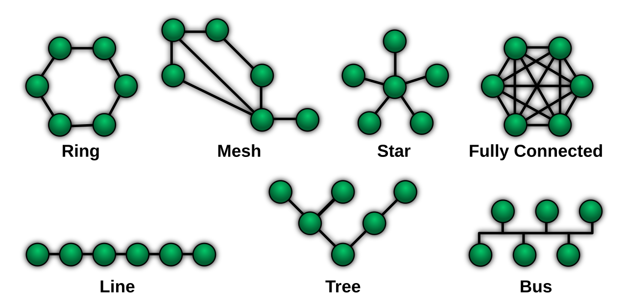
So we put a server in the middle, a star instead of a mesh, so each person uploads once. That leaves the question of what the server does with the streams it receives, and there are two classic answers.
4.2Mix on the server, or forward
An older answer is the multipoint control unit (MCU). It receives every participant's stream, decodes them all, composes a picture (a grid, or the speaker large and the rest small), mixes the audio, encodes the result, and sends each participant one stream. Each person uploads one stream and downloads one. That's ideal for a weak device, and it's how hardware video-conferencing rooms worked for decades.
All the cost lands on the server. Decoding six video streams and encoding new ones is heavy work, and it's per meeting. It also has to encode a slightly different mix for each person (Tom shouldn't see or hear himself), and every decode and re-encode adds delay and loses a little quality.
A newer answer is the selective forwarding unit (SFU). It receives each participant's stream and forwards packets, without decoding them, to whoever should receive them. Each person uploads once and downloads one stream from each person they're watching. The server's work per packet is reading a header and making copies, which is cheap enough that one machine can serve many meetings.
What should sit in the middle of a meeting?
- No server bandwidth to pay for
- Shortest path between each pair
- Each person uploads n − 1 copies
- Needs NAT traversal between every pair
- One stream down: easy on weak devices
- Works with old room systems and phones
- Heavy server CPU per meeting
- Extra delay and quality loss from re-encoding
- Everyone gets the layout the server chose
- Cheap per packet, so many meetings per server
- No re-encoding delay
- Each receiver can get different streams
- Each receiver downloads several streams
- Senders must provide versions for weak receivers
Zoom's 2019 IPO filing makes this argument directly. It describes the MCU as "similar to other mainframe-like approaches where stream processing and mixing run on the same machine, which is resource-intensive and limits scalability", and says Zoom instead built a "multimedia router (MMR)" that "separates content processing from the transporting and mixing of streams", with encoding and decoding done on the client devices. The filing claims each MMR could support about 1,100 more meeting participants than a standard MCU, "which generally supports up to 80 participants". Zoom's current architecture page (2024) puts it as "subscription-based switching without server-side transcoding or mixing", which is an SFU in everything but name. MCU-style mixing survives at the edges: phones dialling in over the telephone network can only take one mixed stream, and Zoom's whitepaper describes connector servers that decode and composite for exactly those cases.
05One stream, many receivers: simulcast and SVC
5.1Receivers differ
The SFU solved the upload problem and created a new one. It forwards whatever it receives, and the receivers are wildly different. Kenji in Tokyo has fibre and a 27-inch screen showing Ananya full size. Tom has about 1.2 Mbps on a train, and a phone screen where Dev, Lucia, Kenji and Sara are thumbnails the size of a postage stamp. If Ananya sends 720p at 1.5 Mbps, Tom can't receive it; if she sends 180p for Tom's sake, Kenji gets a blurry speaker on a big screen.
An MCU would have solved this by encoding a separate stream for each receiver, which is exactly the expensive work we moved off the server. The SFU can't re-encode, so it needs the sender to provide versions of the video that it can choose between by dropping packets. To see how, we need one fact about how video compression works.
5.2How video compression creates dependencies
A video encoder doesn't compress each frame on its own. Consecutive frames of a person talking are nearly identical, so most frames are sent as differences from an earlier one: "the same as the last frame, except this block moved two pixels left". A frame that is compressed on its own, as a complete picture, is an I-frame (or keyframe). A frame stored as differences from an earlier frame is a P-frame. P-frames are many times smaller than I-frames, which is where most of video's compression comes from.

Those dependencies are what make a lost video packet so damaging. Losing a packet of audio costs 20 ms of sound. Losing part of a P-frame corrupts that frame and every frame after it that refers back to it, so the picture smears or freezes until a fresh I-frame arrives. It's also the key to dropping frames safely: if the encoder arranges the references carefully, some frames are never referred to by anything, and a server can drop those without hurting anything else.
5.3Simulcast and SVC
There are two ways for a sender to give the SFU something to choose from.
The first is simulcast: the sender encodes its camera two or three times at once, say 180p, 360p and 720p, and uploads all three as separate streams. The SFU forwards one of them to each receiver: 720p to Kenji, 180p to Tom. This is why Zoom's table in section 1.2 shows a group-call upload bigger than the download. Simulcast costs upload bandwidth and the sender's CPU, which encodes the same picture three times.
The second is scalable video coding (SVC): the sender encodes once, as a stack of layers. Its bottom layer is a complete low-quality video on its own. Each layer above adds something, using the layers below as references:
- Temporal layers add frames. Layer T0 might be 7.5 frames a second; T1 adds the frames in between for 15; T2 adds more for 30. Frames in T2 are never used as references by anything, so dropping them leaves a smooth lower-frame-rate video.
- Spatial layers add resolution. S0 is 180p; S1 is 360p, coded as an improvement on S0; S2 is 720p, coded on top of S1.
A stream with three spatial and three temporal layers is described as L3T3, the naming the W3C uses for WebRTC's SVC settings. Each packet carries its layer IDs in an RTP header extension, so the SFU can read them without decoding anything. SVC was standardised for H.264 in 2007, and it's built into the newer VP9 and AV1 codecs.
How should a sender provide different qualities for different receivers?
- Simplest sender and server
- The weakest receiver sets everyone's quality, or gets nothing
- Works with any codec, including hardware H.264
- Each version decodes on its own
- Uploads every version
- Encodes the same picture several times
- One encode, less upload than simulcast
- Can drop to a lower layer at any frame, no waiting for a keyframe for temporal changes
- Needs a codec and decoder that support layers
- Each layer costs a little compression efficiency
Zoom hasn't published which it uses internally, or how many layers. Its architecture page (2024) says only that "Zoom uses multiple simultaneous streams, and the Zoom Workplace app dynamically selects the most appropriate layer," and its 2019 filing describes clients that "dynamically encode and decode based upon the performance of client technology, network performance and bandwidth." Outside write-ups often describe Zoom's approach as SVC, but Zoom's own documents don't say, so this Decision has no "chosen" mark. What's clear is the shape: senders provide several qualities, and the server chooses per receiver without decoding.
5.4Picking layers for Tom
The SFU now has a decision to make, many times a second, for every receiver: which layer of which sender to forward. It has three inputs. First, what the receiver's screen needs: a postage-stamp thumbnail gains nothing from 720p. Second, who matters most: the active speaker, detected from audio levels, comes first. Third, how much the receiver can download, an estimate that section 7 explains how to get.
A simple, workable algorithm, close to how the open-source SFUs describe theirs, runs in two passes. First, give every visible sender its lowest layer, speaker first, while the budget lasts, so everyone at least appears. Then upgrade one step at a time, always starting again from the most important sender, until nothing more fits or every view has what it needs.
# Each sender uploads three versions of its video. The SFU picks, for each
# receiver, which version of each sender to forward, inside that receiver's
# estimated downlink bandwidth.
LAYERS = [("180p", 0.15), ("360p", 0.5), ("720p", 1.5)]          # name, Mbps

# What Tom's screen shows: Ananya is speaking, so she fills the stage;
# the others are small tiles, where anything above 360p is wasted.
view = [("Ananya", 2), ("Dev", 1), ("Lucia", 1), ("Kenji", 1), ("Sara", 1)]

def allocate(budget):
    chosen = {}
    # pass 1: everyone gets the lowest layer, in priority order, while it fits
    for name, _ in view:
        if LAYERS[0][1] <= budget:
            chosen[name] = 0
            budget -= LAYERS[0][1]
    # pass 2: upgrade one step at a time, speaker first, up to what the view needs
    upgraded = True
    while upgraded:
        upgraded = False
        for name, wanted in view:
            if name in chosen and chosen[name] < wanted:
                extra = LAYERS[chosen[name] + 1][1] - LAYERS[chosen[name]][1]
                if extra <= budget:
                    chosen[name] += 1
                    budget -= extra
                    upgraded = True
                    break            # restart from the speaker after every upgrade
    return chosen, budget

for downlink in (0.5, 1.2, 2.5, 4.0):
    chosen, left = allocate(downlink)
    plan = "  ".join(f"{n} {LAYERS[chosen[n]][0] if n in chosen else 'off':4}" for n, _ in view)
print(f"{downlink:3.1f} Mbps: {plan} (spare {left:.2f})")0.5 Mbps: Ananya 180p Dev 180p Lucia 180p Kenji off Sara off (spare 0.05)
1.2 Mbps: Ananya 360p Dev 180p Lucia 180p Kenji 180p Sara 180p (spare 0.10)
2.5 Mbps: Ananya 720p Dev 360p Lucia 180p Kenji 180p Sara 180p (spare 0.05)
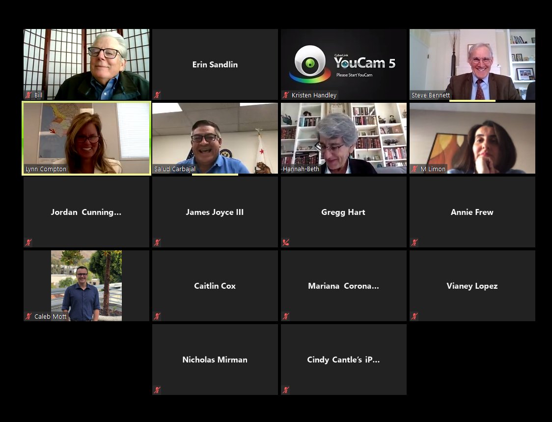
4.0 Mbps: Ananya 720p Dev 360p Lucia 360p Kenji 360p Sara 360p (spare 0.50)Those layer bitrates are illustrative, but the behaviour is the real one. At 0.5 Mbps there isn't room for everyone, so the two lowest-priority tiles go dark (they'd show a name, as in the photo at the top). At 1.2 Mbps, Tom's actual budget, everyone appears and Ananya gets 360p. At 4 Mbps, the thumbnails stop at 360p because the view doesn't need more, and half a megabit is left unused instead of being wasted on pixels nobody can see.
With SVC, carrying out the decision is a filter on each packet: forward it if its spatial layer is at most Tom's target spatial layer and its temporal layer is at most his target temporal layer, and drop it otherwise. There's one subtlety. Moving down a layer can happen at any frame, because the lower layers never depended on the upper ones. Moving up a spatial layer is a bit harder: it has to wait for a frame where that layer starts afresh, otherwise Tom's decoder would receive differences against a picture it never had. So when the budget grows, the SFU asks the sender for a keyframe and switches when it arrives.
06Late packets and lost ones
6.1Jitter, and why the receiver waits on purpose
The SFU now sends Tom the right layers. Packets still have to cross the internet, and they don't arrive evenly. Ananya's laptop sends an audio packet every 20 ms, as regular as a clock. Tom's phone receives them with gaps of 12 ms, 31 ms, 18 ms, 45 ms, 2 ms: each packet waited a different time in the queues of the routers along the way, and Wi-Fi and mobile links add their own retries. Occasionally a later packet overtakes an earlier one. This variation in delay from packet to packet is called jitter.
If Tom's phone played each packet the instant it arrived, the sound would stutter whenever a packet came late, and there'd be nothing to play in the gap. So the receiver deliberately holds packets for a short time before playing them, in a jitter buffer. Every packet is played at a fixed time after it was sent; a packet that arrives early waits, and the buffer absorbs the variation. It costs something plain: every millisecond of buffer is a millisecond added to mouth-to-ear delay, the row in section 1.3's table that the receiver controls.
Inside, the buffer is a small ring buffer: an array of slots, indexed by sequence number modulo the array's size, with a play position that moves forward one slot every 20 ms. A packet goes into its slot whenever it arrives, early or out of order. When the play position reaches a slot, whatever is there is decoded and played. If the slot is empty, the packet is late or lost, and the player must do something else, which section 6.2 covers. A packet that arrives after its slot has been played is thrown away.
How long should the buffer be? Too short, and many packets miss their slot; too long, and the conversation feels sluggish. So the receiver needs a running measure of how variable the arrivals are, and RFC 3550 defines one that every RTP receiver computes. For each pair of consecutive packets, take the difference between how far apart they arrived and how far apart they were sent (from their timestamps), call it D, and update the estimate J by a sixteenth of the way towards |D|:
J ← J + (|D| − J) / 16
Dividing by 16 makes J a smoothed average that follows real changes within a second or so but ignores one-off spikes. It's the jitter figure that goes back to the sender in each RTCP receiver report.
This program simulates a minute of Ananya's audio arriving at Tom's phone, over a path with 90 ms of fixed delay and a variable queueing delay that is usually a few milliseconds and, for 2% of packets, an extra 40 to 120 ms (a Wi-Fi retry, a busy router). It computes the RFC 3550 jitter estimate, then counts how many packets would miss their slot for different buffer lengths:
import random
random.seed(7)

# Ananya's voice: one 20 ms audio packet every 20 ms, for one minute
N, FRAME = 3000, 20
sent = [i * FRAME for i in range(N)]

# The path to Tom: 90 ms of fixed travel time, plus a queueing delay
# that is usually small and sometimes large (Wi-Fi retries, a busy router)
def queueing():
    return random.expovariate(1 / 8) + (random.uniform(40, 120) if random.random() < 0.02 else 0)
arrive = [s + 90 + queueing() for s in sent]

# RFC 3550's running jitter estimate: J += (|D| - J) / 16
J = 0.0
for i in range(1, N):
    D = (arrive[i] - arrive[i - 1]) - (sent[i] - sent[i - 1])
    J += (abs(D) - J) / 16
print(f"RFC 3550 jitter estimate: {J:.1f} ms")

# A jitter buffer plays packet i at sent[i] + 90 + buffer; anything later is useless
for buffer in (0, 10, 20, 40, 60, 100):
    late = sum(a > s + 90 + buffer for s, a in zip(sent, arrive))
print(f"buffer {buffer:3} ms network + buffer {90 + buffer:3} ms late packets {late / N:6.1%}")RFC 3550 jitter estimate: 10.9 ms
buffer 0 ms network + buffer 90 ms late packets 100.0%
buffer 10 ms network + buffer 100 ms late packets 30.4%
buffer 20 ms network + buffer 110 ms late packets 10.4%
buffer 40 ms network + buffer 130 ms late packets 2.8%
buffer 60 ms network + buffer 150 ms late packets 2.0%
buffer 100 ms network + buffer 190 ms late packets 0.7%Read the table from the top. With no buffer at all, every packet is "late", because any queueing delay at all means it missed a schedule with no slack. Ten milliseconds of buffer still loses almost a third of the packets, and 20 ms loses a tenth. Around 40 ms, roughly four times the measured jitter, the losses drop to under 3%. After that each extra 20 ms of delay buys very little, because what's left are the rare big spikes, and catching those would mean adding 100 ms of delay to every packet for the sake of 2% of them.
That's why real jitter buffers adapt. WebRTC's audio receiver, NetEq, keeps the buffer near the smallest size that covers the recent jitter, and shrinks or stretches it gradually by playing speech very slightly faster or slower, which listeners don't notice. And it's why the remaining 2% of packets need a different answer from waiting.
6.2Repairing losses: ask again, send extra, or guess
Some packets never arrive, and some arrive too late to be any use. There are three ways to deal with them, and they suit different situations.
Ask for it again. The receiver tells the sender which packets it's missing, and the sender resends them. RFC 4585 (2006) defines the standard request, the generic NACK ("negative acknowledgement"), and its layout is a neat little data structure. Each entry is 32 bits: a 16-bit packet ID (PID), the first missing sequence number, and a 16-bit bitmask (BLP) of which of the next sixteen packets are also missing, where bit i means PID + i + 1. If Tom is missing 1001, 1003 and 1004, one entry covers all three: PID = 1001, and bits 1 and 2 are set, so BLP = 0x0006. Asking again is efficient, since only lost packets are resent. But it takes at least a round trip, and that only helps if the receiver's buffer is longer than the round trip. For audio between Bengaluru and London it probably isn't. For video it often pays off, because one repaired packet saves a whole chain of P-frames from corruption.
Send something extra in advance. The sender adds redundant data so the receiver can rebuild a lost packet without asking. This is forward error correction (FEC). The simplest form, used in RFC 5109 (2007) and its successor FlexFEC (RFC 8627, 2019), is XOR parity: after packets 1 to 4, send a fifth packet that is all four XORed together. If any one of the four is lost, XORing the other three with the parity packet gives it back. It works instantly, but it costs bandwidth all the time, here 25% more, even when nothing is lost. Opus has its own version for audio: each packet can carry a low-bitrate copy of the previous one, so a single lost packet can be rebuilt from the next.
Guess. When nothing else works, the decoder makes up something plausible for the missing 20 ms: it repeats and gradually fades the last bit of sound, keeping the pitch of the voice. This is packet loss concealment (PLC). For video, the equivalent is to keep showing the last good frame and ask the sender for a fresh keyframe with a picture loss indication (PLI, also in RFC 4585) when the damage is too great.
| Technique | Cost | Delay | Best for |
|---|---|---|---|
| NACK and resend | Only lost packets resent | At least one round trip | Video, short round trips |
| FEC (parity, Opus in-band) | Extra bandwidth all the time | None | Audio, long round trips, random loss |
| Concealment (PLC) | Nothing sent | None | The last resort, for short gaps |
| Keyframe request (PLI) | One large frame | A round trip, plus a big frame | Video after heavy loss |
07How fast to send
7.1The network doesn't say how much it can take
Every decision so far assumed the system knows Tom's bandwidth. It doesn't, and neither does Tom's phone. Nothing on the internet tells a sender how fast it may send. A path's bottleneck might be the phone's radio link, a congested cell tower, or a busy router in another country, and its capacity changes as the train moves.
If Tom's phone sends faster than the bottleneck can carry, the excess waits in the queue of the router in front of the bottleneck. The queue grows, every packet waits longer, and only when the queue is full does the router start dropping packets. TCP's classic congestion control waits for those drops before slowing down. For a file download that's fine. For a call it's far too late: by the time packets are being dropped, the queue may already hold a few hundred milliseconds of data, and every word Tom says is that much later.
So real-time media uses a congestion controller that watches delay, and backs off when it sees the queue starting to grow, before anything is lost. The best-documented one is Google Congestion Control (GCC), used in WebRTC and described in an IETF draft (draft-ietf-rmcat-gcc-02, July 2016).
7.2Google Congestion Control
GCC runs two controllers side by side and sends at the lower of their two estimates.
The delay-based controller looks at how packets spread out on the way. Tom's side records when each packet arrived. If a group of packets that left the sender 5 ms apart arrives 7 ms apart, the extra 2 ms was spent in a queue that's growing. GCC smooths these differences and compares the trend with a threshold. The draft recommends starting the threshold at 12.5 ms and adapting it so the controller isn't fooled by noise. The result is one of three signals: over-use (the queue is growing), under-use (the queue is draining), or normal. A small state machine turns the signal into a rate:
- Increase: while the signal is normal, raise the rate, by at most 8% per second (multiplied by 1.08 per second of elapsed time). Close to the last known limit, it switches to adding about half a packet per round trip, to creep up gently.
- Decrease: on over-use, set the rate to 0.85 times the rate the receiver reports getting. That drops below what the bottleneck can carry, so the queue drains.
- Hold: while the queue drains, keep the rate unchanged, then return to increase.
The loss-based controller is a backstop for links where delay doesn't rise before loss, such as some wireless links. If more than 10% of packets are lost, it cuts its estimate by half the loss fraction; if less than 2% are lost, it raises the estimate by 5%; in between it holds. Loss below 2% is treated as noise, not congestion.
GCC's original draft ran the delay-based controller at the receiver, which then sent its estimate back to the sender. Later versions of WebRTC moved the whole calculation to the sender: the receiver just reports when each packet arrived, using a transport-wide congestion control feedback message, and the sender does the arithmetic.
This program runs a simplified version of the delay-based controller. Tom's uplink can carry 2.5 Mbps until, five seconds in, his train reaches a crowded station and the link drops to 1.0 Mbps for ten seconds. Every 100 ms a feedback report tells the sender how much got through and how full the queue is. It simplifies two things: a fixed 1 ms threshold on the change in queueing delay, in place of GCC's adaptive one, and no additive phase near the limit:
# Tom's uplink carries 2.5 Mbps until his train reaches a crowded station,
# where it drops to 1.0 Mbps for ten seconds. A simplified version of GCC's
# delay-based controller decides how fast his phone sends video.
def capacity(t):
    return 1.0 if 5 <= t < 15 else 2.5            # Mbps

TICK = 0.1                                        # one feedback report every 100 ms
rate = 2.0                                        # Mbps Tom's phone is sending
queue = 0.0                                       # megabits waiting at the bottleneck
prev_delay, state = 0.0, "increase"

for step in range(int(25 / TICK)):
    t = step * TICK
    c = capacity(t)
    drained = min(c * TICK, queue + rate * TICK)  # what the link carried this tick
    queue += rate * TICK - drained
    received = drained / TICK                     # the rate the receiver saw
    delay = queue / c * 1000                      # ms a new packet now waits

    gradient = delay - prev_delay                 # is the queue growing or shrinking?
    prev_delay = delay
    if gradient > 1.0:                            # over-use: back off, then hold
        if state != "hold":
            rate = 0.85 * received                # GCC: 0.85 x the rate that got through
        state = "hold"
    elif gradient < -1.0 or delay > 5:            # queue still draining: hold
        state = "hold"
    else:                                         # normal: probe upwards
        state = "increase"
        rate *= 1.08 ** TICK                      # GCC: at most +8% per second

    if step % 10 == 0 or step in (51, 52):
        print(f"t={t:4.1f}s  link {c:.1f}  sending {rate:4.2f}  "
f"received {received:4.2f} Mbps queue {delay:4.0f} ms {state}")t= 0.0s link 2.5 sending 2.02 received 2.00 Mbps queue 0 ms increase
t= 1.0s link 2.5 sending 2.18 received 2.16 Mbps queue 0 ms increase
t= 2.0s link 2.5 sending 2.35 received 2.33 Mbps queue 0 ms increase
t= 3.0s link 2.5 sending 2.54 received 2.50 Mbps queue 1 ms increase
t= 4.0s link 2.5 sending 2.26 received 2.24 Mbps queue 0 ms increase
t= 5.0s link 1.0 sending 0.85 received 1.00 Mbps queue 142 ms hold
t= 5.1s link 1.0 sending 0.85 received 1.00 Mbps queue 127 ms hold
t= 5.2s link 1.0 sending 0.85 received 1.00 Mbps queue 112 ms hold
t= 6.0s link 1.0 sending 0.85 received 0.92 Mbps queue 0 ms hold
t= 7.0s link 1.0 sending 0.92 received 0.91 Mbps queue 0 ms increase
t= 8.0s link 1.0 sending 0.99 received 0.98 Mbps queue 0 ms increase
t= 9.0s link 1.0 sending 0.88 received 0.88 Mbps queue 0 ms increase
t=10.0s link 1.0 sending 0.95 received 0.95 Mbps queue 0 ms increase
t=11.0s link 1.0 sending 0.85 received 0.87 Mbps queue 0 ms hold
t=12.0s link 1.0 sending 0.92 received 0.91 Mbps queue 0 ms increase
t=13.0s link 1.0 sending 0.99 received 0.98 Mbps queue 0 ms increase
t=14.0s link 1.0 sending 0.88 received 0.88 Mbps queue 0 ms increase
t=15.0s link 2.5 sending 0.95 received 0.95 Mbps queue 0 ms increase
t=16.0s link 2.5 sending 1.03 received 1.02 Mbps queue 0 ms increase
t=17.0s link 2.5 sending 1.11 received 1.10 Mbps queue 0 ms increase
t=18.0s link 2.5 sending 1.20 received 1.19 Mbps queue 0 ms increase
t=19.0s link 2.5 sending 1.30 received 1.29 Mbps queue 0 ms increase
t=20.0s link 2.5 sending 1.40 received 1.39 Mbps queue 0 ms increase
t=21.0s link 2.5 sending 1.51 received 1.50 Mbps queue 0 ms increase
t=22.0s link 2.5 sending 1.64 received 1.62 Mbps queue 0 ms increase
t=23.0s link 2.5 sending 1.77 received 1.75 Mbps queue 0 ms increase
t=24.0s link 2.5 sending 1.91 received 1.89 Mbps queue 0 ms increaseThere are four things to notice, in order. In the first three seconds the sender probes upwards by 8% a second, and at t = 3.0 it touches the link's 2.5 Mbps: a millisecond of queue appears, and it backs off to just under the limit. That's the controller finding the ceiling without a single packet lost. At t = 5.0 the link drops to 1 Mbps, and in that first 100 ms a 142 ms queue builds up, roughly how long Tom's voice would now lag. The next report shows the queue growing, so the sender drops to 0.85 times what got through, 0.85 Mbps, and the queue drains within a second. From t = 6 to 15 it saws gently between 0.85 and 1.0 Mbps, never far from the link's real capacity and never building a queue that lasts. And after t = 15, when the link recovers, it climbs back slowly: 8% a second takes roughly ten seconds to get from 1 to 2 Mbps.
That last point is a real weakness, and a deliberate one. Climbing faster would probably find the new capacity sooner, but it would overshoot more often and build queues that hurt everyone sharing the link. Some controllers probe more aggressively by sending padding or FEC packets as "test traffic", and drop them as soon as delay rises. The SFU side has the same problem in the other direction: it estimates each receiver's download bandwidth from that receiver's feedback, and the result is the budget that section 5.4's layer allocator splits up.
?What does Zoom use?
Zoom hasn't published its congestion controller. Its 2019 filing describes "proprietary algorithms that detect packet loss, latency, jitter, CPU utilization and bitrate/bandwidth to optimize the video, audio and content sharing experience," and says the client weighs those factors differently depending on the device. That's the same family of design as GCC: measure the path continuously, from the receiver's reports, and adjust the encoder's rate and the layers sent, instead of waiting for loss.
08Where the meeting lives
8.1Which server, in which city?
So far "the media server" has been a single box. Any real server sits in some city, and section 1.3 showed that distance costs time that nothing else can recover. Ananya is in Bengaluru, Tom in London, Lucia in São Paulo, Kenji in Tokyo and Sara in Toronto. Wherever the server is, somebody is far from it.
A naive placement hosts each meeting on a server near whoever started it. For Ananya's meeting that's India, and Lucia's audio goes from São Paulo to India and back to Toronto, crossing the planet twice to reach someone in the same hemisphere. If every meeting started in one region lives there, that region's capacity also has to cover every meeting its users start, however global.
A better approach connects each participant to a server near them, and connect those servers to each other. Tom's phone talks to a server in Europe, Lucia's laptop to one in South America, and the servers exchange streams over links between data centres. Each participant's first hop is short, which keeps their own loss and jitter low, and the long-haul part of the journey runs over well-provisioned links between data centres, instead of across the public internet from someone's home. This is called cascading, and it has a useful property: a European server receives Ananya's stream once, however many Europeans are in the meeting, and makes the copies locally.
Where should a meeting's media be handled?
- Simple: one place knows everything
- No server-to-server traffic
- Far-away participants cross the public internet the whole way
- One meeting is limited to one machine
- Short, clean first hop for everyone
- Long-haul traffic on private links
- Meetings can grow past one machine
- Servers must agree on who sends what to whom
- An extra forwarding hop between servers
Zoom's 2019 filing says it served real-time traffic from "13 co-located data centers" on its own servers, with "a network of private links so that each data center connects to multiple others", and that its "geographically distributed architecture enables users to connect to the data center closest to their location." Its architecture page (2024) adds that "participants are routed by geolocation to the nearest data center and assigned to the least-loaded server," and describes "cascaded traffic paths" for large deployments. Exactly how Zoom splits one meeting across data centres isn't published.
8.2Controllers, zones and the 2020 surge
Someone has to decide where each participant goes, so the media servers are organised in a hierarchy. Zoom's architecture page describes three levels: the MMRs that carry media; meeting zones, groups of MMRs in a data centre, each managed by a zone controller that tracks their load; and a global cloud controller above the zone controllers, which picks a zone for each participant. A media server only has to know about its own meetings. Controllers only handle joins and load reports, not media, so they see a tiny fraction of the traffic.
That structure was tested in spring 2020, when daily participants grew from about 10 million to 300 million in four months. The 2019 design put real-time media in Zoom's own co-located data centres and used public clouds (Amazon Web Services and Microsoft Azure) only for web and messaging. Under the surge Zoom also ran meeting capacity in public clouds; in April 2020 Oracle announced that Zoom had chosen Oracle Cloud for part of its core meeting service. Zoom's architecture page says it keeps "50% excess capacity in all aspects of our infrastructure".
Placement also turned out to be a legal question. The Citizen Lab's April 2020 report found that some meetings between participants outside China had their keys handed out through servers in China. On 18 April 2020 Zoom let paid accounts choose which data-centre regions their meeting traffic could pass through, and made China opt-in. A placement algorithm that only optimised latency had broken a promise nobody had written down: where your data goes.
09A meeting the servers can't watch
9.1Encrypting each hop
A media server reads headers to route packets. Does it need to read the media? The easy answer is to encrypt each hop: every participant shares a key with the server, encrypts what it sends, and the server decrypts, routes, and re-encrypts for each receiver. That protects the call from someone on the café Wi-Fi, but the server, and anyone who breaks into it, sees and hears everything.
Zoom's own history shows how this goes wrong, with dates. Its March 2019 IPO filing listed "end-to-end encryption" among its security features. On 3 April 2020 the Citizen Lab reported what it found on the wire: a single AES-128 key (AES is the standard cipher for bulk data) shared by all participants, used in ECB mode, which encrypts identical blocks of input to identical blocks of output and so preserves patterns in the data, with the key generated and handed out by Zoom's servers. Zoom's use of "end-to-end" had meant encryption between each device and Zoom's servers. On 22 April 2020 Zoom 5.0 switched to AES-256 in GCM mode, which both hides patterns and detects tampering, and turned GCM on across its whole system on 30 May.
AES-GCM fixed the cipher. It didn't change who held the key. In what Zoom now calls enhanced encryption, its current default, the whitepaper says each client gets "a 256-bit per-meeting key (MK) generated by the Zoom server", and the media servers don't decrypt media to route it. They don't need to, since routing uses headers. But Zoom's infrastructure has the key, and it uses it on purpose for cloud recording, live captions, and phone dial-in, where a connector server decodes and mixes for a phone that can't take anything else.
9.2End-to-end: the key never reaches the server
End-to-end encryption (E2EE) means only the participants' devices ever hold the key. Zoom bought the encryption company Keybase in May 2020 and shipped end-to-end encrypted meetings on 26 October 2020, at first for up to 200 participants. Zoom published the design in its Cryptography Whitepaper on GitHub (version 4.7, June 2025), which is unusual for a commercial product and lets us go down to the protocol.
At its base is the same building block WhatsApp uses (chapter 49, section 7): a Diffie–Hellman key exchange, in which two devices that have swapped public keys can each compute the same shared secret, while someone who saw both public keys can't.
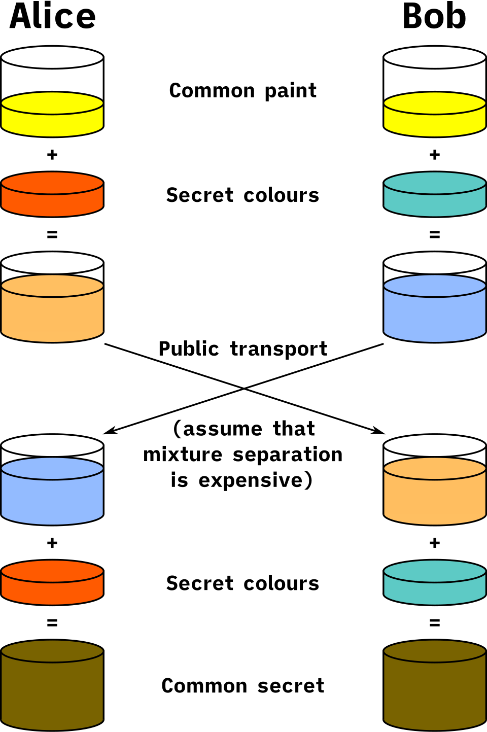
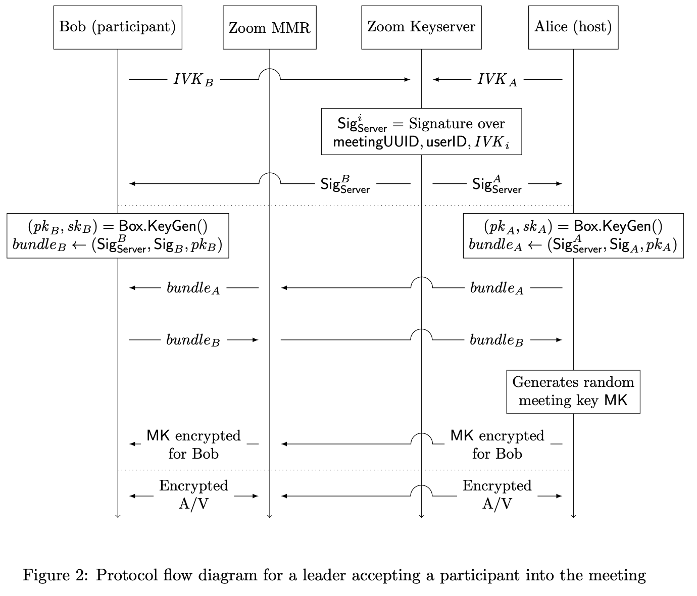
A group call needs one key that all six devices share, and no server can generate it. Zoom's protocol gives that job to one participant, the meeting leader, usually the host's device, chosen by the server and replaced if it leaves. Here's what happens when Tom joins Ananya's end-to-end encrypted meeting, with Ananya's laptop as leader:
- Every device has a long-term signing key pair. Its public half, the IVK, is registered with Zoom's key server.
- Tom's phone generates a fresh, temporary encryption key pair just for this meeting. It signs a statement binding together the meeting ID, a random per-meeting UUID chosen by the server, its user and device IDs, its IVK and the new public key, and posts the statement to the meeting's "bulletin board", a channel that every participant can read.
- Ananya's laptop fetches Tom's IVK from the key server, checks the signature, and so knows the new public key belongs to Tom's device in this meeting.
- It encrypts the meeting key for Tom using Diffie–Hellman between its own temporary key and Tom's, and posts the result to the bulletin board.
- Tom's phone decrypts it. Now it can encrypt and decrypt media with AES-256-GCM, using keys derived from the meeting key, with a separate key for each sender and each type of data.
?What stops the server from inserting itself?
The server relays every one of those messages, so it could try to substitute its own public key for Tom's. Two things stop it. Step 3 checks Tom's signature against the IVK from the key server, so a fake key would need a fake IVK too. And to catch a fake IVK, the client shows a meeting leader security code: 39 decimal digits derived by SHA-256 from the leader's IVK. Ananya reads hers out loud, and everyone checks their screen shows the same digits. If the server had given someone a different leader key, their code wouldn't match.
?What happens when someone leaves?
A person who has left still knows the meeting key. So the leader generates a brand new, independent meeting key whenever someone joins or leaves, and also every five minutes regardless, and sends it to the current participants only. Each key has a sequence number, and every encrypted packet carries the 4-byte number of the key it used. Devices wait about two seconds before switching, so nobody is cut off mid-sentence, and stop accepting the old key ten seconds after receiving a new one. Ananya's laptop also broadcasts a signed list of current participants at least every ten seconds, and a device that misses ten of these in a row leaves the meeting, so a server can't quietly withhold a membership change.
Compare that with WhatsApp's groups (chapter 49), where each sender has its own key and hands it to every member pairwise. Zoom's single leader-distributed key suits a live meeting: membership changes are rare compared with the number of packets, and one key change per join keeps the work small even with hundreds of people.
Who should hold a meeting's key?
- Cloud recording, live captions, transcripts
- Phone and SIP dial-in, browser clients
- Joining is simple
- Anyone controlling the servers can decrypt
- The servers can't decrypt media
- Rekeys on every join and leave, and every 5 minutes
- No cloud recording or phone dial-in
- Only official Zoom clients can join
- Participants must check a security code to rule out a lying server
Zoom offers both and lets the host choose per meeting; the choice can't change once the meeting starts. That's an honest statement of the tradeoff: every feature that needs a server to understand the media (recording, captions, a phone that can only take a mixed stream) is incompatible with the server not having the key. Since client version 6.3.0 (May 2024, whitepaper version 4.4), the key exchange combines X25519 with Kyber768, a post-quantum algorithm, so recorded traffic stays safe even against a future quantum computer.
Even with end-to-end encryption, the SFU still works, because everything it needs is outside the encrypted payload: which stream a packet belongs to, its sequence number, and its layer IDs. That has a consequence. The server, and anyone watching the network, still sees who is in the meeting, when they talk, and how much each person sends. The 2022 Princeton study measured the frame rates, bitrates and jitter of real Zoom calls from packet headers alone.
10The whole system
10.1Every box, and why it's there
| Component | What it does | Added because |
|---|---|---|
| RTP over UDP | Numbers and timestamps each packet; losses cost only themselves | TCP stalls everything behind a loss (§2) |
| STUN, TURN, ICE | Find a path through NATs | Private addresses can't be reached from outside (§3) |
| Media servers (SFU) | Forward packets without decoding | Mesh upload grows with meeting size; MCUs are costly (§4) |
| Simulcast or SVC layers | Several qualities from each sender | Receivers' bandwidth and screens differ (§5) |
| Layer allocator | Picks layers per receiver within a budget | The speaker matters most; thumbnails need little (§5.4) |
| Jitter buffer | Holds packets briefly, plays them on a clock | Packets arrive unevenly and out of order (§6) |
| NACK, FEC, PLC | Repair or hide losses | Some packets never arrive in time (§6.2) |
| Bandwidth estimation | Sets the sending rate from delay and loss | The network never says how fast to send (§7) |
| Controllers and cascading | Place participants near servers; link servers | Distance costs time; meetings span continents (§8) |
| Meeting key from a leader | End-to-end encryption for a group | Servers shouldn't be able to watch (§9) |
10.2From top to bottom
| Level | The choice | Data structure or algorithm |
|---|---|---|
| System | Spend the time budget carefully | A latency budget: ~150 ms mouth-to-ear, 40 ms of it physics on a long route |
| Transport | Lose a packet instead of waiting | UDP datagrams; 12-byte RTP header; 16-bit sequence numbers compared modulo 2¹⁶ |
| Connectivity | Try every path, best first | ICE candidate priority 2²⁴·type + 2⁸·local + (256 − component) |
| Topology | Forward, don't mix | Per-meeting table of senders to receivers in each SFU |
| Quality | Senders provide layers | Spatial and temporal layer IDs in a header extension; a two-pass allocator |
| Receiver | Play on a clock | Ring buffer indexed by sequence number; RFC 3550 jitter J += (|D| − J)/16 |
| Loss | Repair if there's time, else guess | NACK's PID + 16-bit bitmask; XOR parity FEC; concealment |
| Rate | Back off on delay, not loss | GCC: ×1.08 per second up, ×0.85 of received rate down, min of delay and loss estimates |
| Placement | Nearest data centre, least-loaded server | Global controller → zone controllers → media servers; cascade links |
| Security | Key from a participant, not the server | Signed ephemeral keys, Diffie–Hellman boxes, rekey on join/leave and every 5 minutes |
11What goes wrong, and what it cost
11.1Failures this design has to survive
| What happens | What the user sees | What the design does |
|---|---|---|
| A burst of packet loss on Tom's link | A short glitch in sound, a blocky frame | FEC and concealment cover audio; NACK or a keyframe request repairs video |
| Tom's bandwidth halves on the train | Video drops to a lower resolution for a while | Delay rises first; the estimator backs off; the SFU forwards lower layers |
| A corporate firewall blocks UDP | The call works with a little more delay | The client falls back to TCP/TLS on port 443 |
| A media server crashes | A few seconds of frozen video, then it resumes | Clients reconnect; the controller places them on another server |
| The leader leaves an E2EE meeting | Nothing, or a short pause | The server picks a new leader, which issues a new key; participants are asked to recheck the security code |
| Someone leaves an E2EE meeting | They're shown as present for a few seconds | The leader rekeys within about 10 seconds, so they can't follow what's said next |
11.2The tradeoffs, in one table
| Decision | Chosen | Given up | Why it was worth it |
|---|---|---|---|
| Transport | UDP and RTP | Guaranteed delivery | A late packet is worthless; a lost one only costs itself |
| Topology | SFU in the middle | Mixing on the server | Cheap forwarding scales; each receiver can be served differently |
| Qualities | Layers from each sender | Some upload and compression efficiency | Weak and strong receivers in the same meeting |
| Jitter buffer | Short and adaptive | The rarest late packets | Every millisecond of buffer is added to the conversation's delay |
| Rate control | Back off on rising delay | Some throughput, slower recovery | Queues stay short, so speech stays on time |
| Placement | Nearest data centre, cascaded | Simplicity of one server per meeting | Short first hops and private long-haul links |
| Encryption | Host's choice: enhanced or E2EE | Recording, captions and dial-in under E2EE | Some meetings must be unreadable even to the provider |
12Summary
- A call is governed by time: a mouth-to-ear budget of about 150 ms, of which a long route spends 40 ms or more on the speed of light alone.
- TCP turns one lost packet into a stall of at least a round trip, so live media goes over UDP, with RTP's sequence numbers and timestamps to restore order and timing.
- NAT hides most devices, so calls use STUN to discover public addresses, TURN to relay when nothing else works, and ICE to try every path best first; a media server everyone dials out to avoids most of this.
- A full mesh needs each person to upload n − 1 copies, so meetings go through a server; an SFU forwards without decoding, which is far cheaper than an MCU that mixes.
- Receivers differ, so senders provide layers: simulcast sends several encodings, SVC one layered encoding, and the SFU drops what each receiver can't use.
- The SFU allocates each receiver's bandwidth: lowest layer for everyone first, then upgrades with the speaker first, capped by what each tile on screen needs.
- A jitter buffer trades delay for smoothness: a ring buffer indexed by sequence number, sized from RFC 3550's running jitter estimate and kept as short as possible.
- Losses are repaired three ways: resend on NACK when there's time, send FEC in advance when there isn't, and conceal what's left.
- Congestion control for media watches delay: GCC backs off to 0.85 of the received rate when queues grow and climbs at most 8% a second, so speech stays on time.
- Participants join nearby data centres, and servers cascade over private links; placement also has to respect where a customer's data may go.
- End-to-end encryption moves the key to a participant: Zoom's leader hands a fresh meeting key to each device, rekeys on every change, and a spoken security code catches a lying server.
13Build this
A tiny SFU and its receivers.
- Write a UDP server in Python that accepts "join" messages and then forwards every datagram it receives to every other joined address, without reading the payload. That's an SFU.
- Write a sender that sends a 12-byte RTP header (use
struct.pack("!BBHII", ...)) plus a dummy payload every 20 ms, and a receiver that tracks sequence numbers, counts losses and reorders, and computes RFC 3550 jitter. - Run them on one machine and add impairment with
tc qdisc add dev lo root netem delay 80ms 20ms loss 2%on Linux (or a Python proxy that delays and drops packets on macOS). Watch the jitter estimate and the loss count change. - Add a jitter buffer to the receiver: a ring buffer of 16 slots and a play clock. Measure how many packets miss their slot for buffers of 20, 40 and 80 ms, and compare with the simulation in section 6.
- Have the sender tag each packet with a "layer" 0, 1 or 2, and make the SFU drop layers above a per-receiver limit that you lower whenever the receiver reports rising jitter.
14Interview questions
beginnerWhy do video calls use UDP instead of TCP?›
TCP delivers every byte in order, so when one packet is lost, everything after it waits until the lost one has been resent, which takes at least a round trip. For a live conversation a late packet is worthless, because its moment to be played has passed. UDP lets each packet stand alone: a loss costs only that packet, and the application decides whether to conceal it, repair it from redundant data, or ask for it again. Calls still fall back to TCP on port 443 when a network blocks UDP, because a slightly worse call beats none.
beginnerWhat is a jitter buffer, and what does it cost?›
Packets sent at even intervals arrive unevenly, because each one waits a different time in router queues. A jitter buffer holds incoming packets briefly and plays each one at a fixed time after it was sent, so early packets wait and moderately late ones still make it. The cost is that the buffer's length is added directly to the conversation's delay, so receivers keep it as short as the recent jitter allows, adapt it continuously, and conceal the rare packets that arrive too late.
intermediateCompare mesh, MCU and SFU for a ten-person video call.›
In a mesh, each person uploads nine copies of their video, which ordinary upload links can't sustain. An MCU receives everyone's stream, decodes, mixes one picture per person and re-encodes: each person uploads and downloads one stream, but the server does heavy work per meeting, adds delay and loses quality. An SFU forwards packets without decoding: each person uploads once and downloads the streams they watch, the server's work per packet is small, and because each receiver gets separate streams the server can pick a different quality for each. That last property, with simulcast or SVC, is why Zoom and most modern systems use SFUs.
intermediateHow does a video call find out how much bandwidth it can use?›
It estimates continuously from feedback. The receiver reports when each packet arrived; if packets are spreading out on the way, a queue is growing at the bottleneck, which means the sender is going too fast. Google Congestion Control backs off to 0.85 times the rate getting through when it sees that, holds while the queue drains, then increases by at most 8% a second. A loss-based controller runs alongside and the sender uses the lower of the two. Reacting to delay keeps queues, and therefore speech delay, short, because by the time packets are being dropped the queue already holds hundreds of milliseconds.
deepHow can a group call be end-to-end encrypted when all media goes through a server?›
The server only needs packet headers to route, so the media payload can be encrypted with a key the server never has. In Zoom's design, one participant's device, the leader, generates a random meeting key. Each joining device posts a signed, temporary public key; the leader checks the signature against the device's registered identity key and sends the meeting key encrypted with Diffie–Hellman for that device alone. The leader rekeys on every join or leave and every five minutes, and participants compare a security code derived from the leader's identity key to detect a server that substituted keys. The cost is every feature that needs the server to understand media: cloud recording, captions and phone dial-in.
deepWith SVC, why can the SFU drop to a lower layer instantly but has to wait to switch up?›
Lower layers never refer to higher ones, so removing the upper layers leaves a stream the receiver can still decode from the next frame on. Switching up means sending frames coded as differences against higher-layer pictures the receiver never received, which it can't decode. So the SFU waits for, or requests, a frame where the higher layer starts afresh, a keyframe or a switching point, before it starts forwarding that layer.
15Go deeper
A receiver gets RTP sequence numbers 65,534, 65,535, 2, 3. How many packets are missing?›
Two: 0 and 1. Sequence numbers wrap at 65,536, so after 65,535 comes 0. Comparing them modulo 2¹⁶ is what lets the receiver see that 2 comes after 65,535 and not long before it.
Tom is missing packets 2000, 2002 and 2005. What does one generic NACK entry contain?›
PID = 2000, and a bitmask with bit i set for packet 2000 + i + 1: 2002 is bit 1 and 2005 is bit 4, so BLP = 0b10010 = 0x0012.
Why does a meeting leader in Zoom's E2EE design rekey when someone leaves?›
The person who left still knows the old meeting key and could decrypt anything sent with it. A fresh, independently generated key, sent only to the remaining participants, shuts them out within about ten seconds.
The full end-to-end encryption design, with the leader join protocol, key rotation, security codes and post-quantum key exchange. github.com/zoom/zoom-e2e-whitepaper.
The RTP header, RTCP receiver reports and the jitter estimator, with sample code in the appendix.
How endpoints gather candidates, prioritise them and check connectivity through NATs.
The delay-based and loss-based controllers, the over-use detector and the recommended constants.
Zoom's packet format, reverse-engineered: RTP inside a proprietary header, peer-to-peer versus SFU, and what headers reveal.
What Zoom's encryption looked like on the wire before the 5.0 release, and how keys were distributed.
How open-source SFUs model producers and consumers, choose simulcast and SVC layers, and share a receiver's bandwidth between streams.
16Related chapters
TCP's stream and UDP's datagrams, and what the kernel does with each packet. Chapter 10.
The TLS that protects signalling, and anycast for reaching a nearby server. Chapter 35.
Diffie–Hellman, the Signal protocol and per-sender group keys, the other way to encrypt a group. Chapter 49.
Why queues grow when arrivals exceed service, the effect a congestion controller is trying to avoid. Chapter 42.
Choosing the least-loaded server, the job of Zoom's zone controllers. Chapter 34.